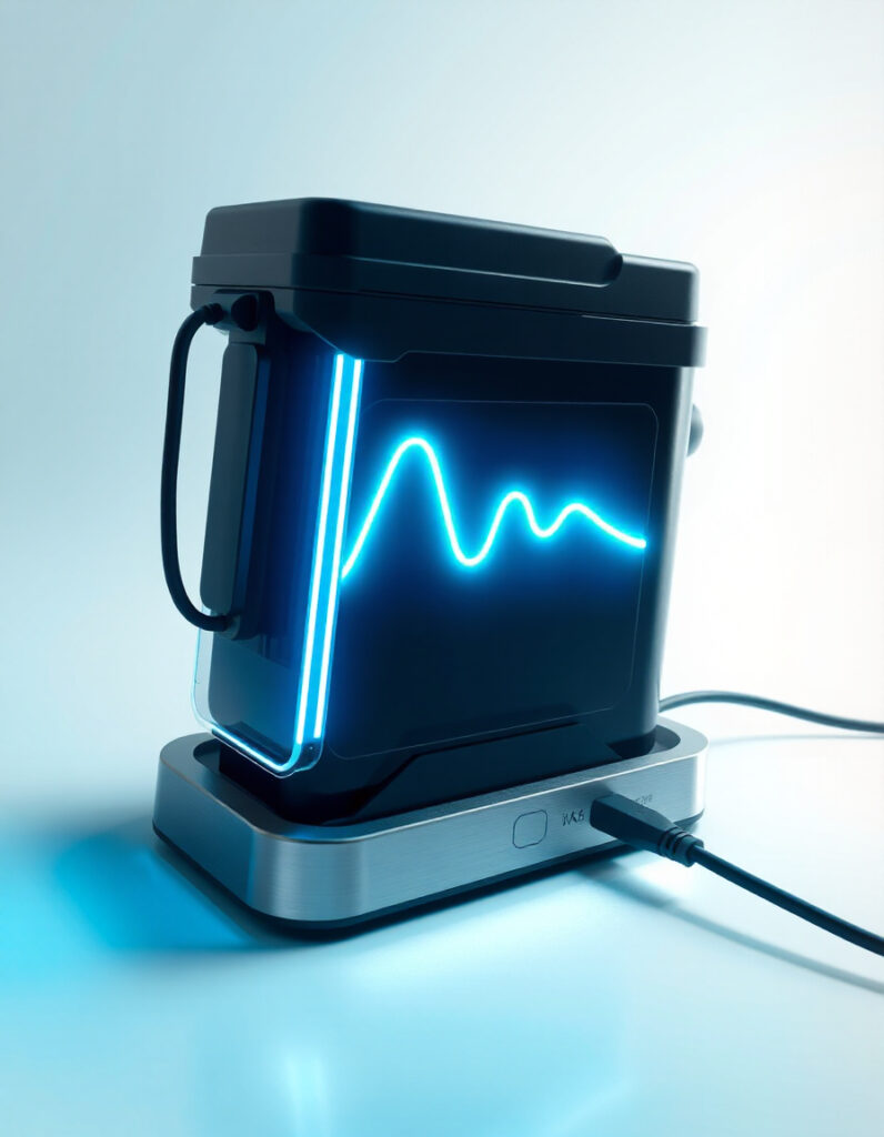
🔌 Charging Curve Simulator
The Charging Curve Simulator models CC→CV charging for e-bike packs, visualizing voltage and current versus time,
estimating CC/CV durations, delivered Ah, and energy. Use it to optimize charging strategies, select safe currents, and show expected charge times.
⚡ How It Works
- CC Phase: constant current; voltage rises as SoC increases.
- CV Phase: voltage constant; current tapers to cutoff.
- Visualizes V vs time, I vs time, CC/CV durations, Ah and energy delivered.
- Includes presets for 36V/48V/52V packs and NMC/LFP chemistries.
🏁 Practical Scenarios
- Product pages: show expected charging times at common currents.
- Design checks: test CC currents for optimal CC/CV balance.
- Customer info: provide “Time to 80% / Time to 100%” examples.
- Education: demonstrate voltage curve differences between NMC and LFP.
🛠 How to Use the Tool
- Select a preset (36V/48V/52V) for nominal voltage & CV settings.
- Choose chemistry: NMC (gradual voltage rise) or LFP (flat mid-voltage).
- Set pack capacity (Ah) and starting SoC (0–1).
- Enter CC current (manufacturer-recommended, 0.2C–1C typical).
- Set CV cutoff current (e.g., 0.1C).
- Run simulation and view graphs & stats.
- Export CSV/JSON for plotting or analysis.
📊 Interpreting Results
- Short CC, long CV: charger voltage-limited; long taper.
- Long CC, short CV: small CC brings pack mostly full before CV.
- Total Ah ≈ CC Ah + CV Ah; energy depends on voltage integration.
- Time to 80% vs 100%: CV tail makes 100% longer; use Ah/SoC to estimate midpoints.
⚠️ Limits & Accuracy
Simulator provides rough visualization only. It does not model:
- Temperature effects on IR and charging current.
- Detailed cell resistance, polarization, plateaus beyond chemistry curves.
- BMS safety cutouts, balancing, or max charge limits.
- Cell aging or capacity fade.
- Exact manufacturer curves.
Always validate critical designs with datasheets and real tests.
💡 Advanced Tips
- Use chemistry model for realistic CV voltage.
- Try different CC currents to optimize charge time vs CV tail.
- Adjust tau to reflect faster/slower CV taper.
- Export CSV for Excel or custom plots.
📝 Developer Notes
- Outputs time, V, I, SoC for analysis.
- Import per-cell SoC→Voltage tables for more accurate curves.
- Add BMS presets for realistic simulations.
- Optionally model temperature using V = OCV + I*R_internal.
📌 Example Workflows
- Support page: show charging times for 48V pack at 2A charger (20%→80% ≈ 2h).
- Charger selection: compare CC=5A vs CC=10A for total charge time vs CV tail trade-off.
⚠️ Safety Note
Use for visualization & planning only. For safety-critical decisions, consult battery/charger/BMS datasheets and perform controlled tests.