Charging Time Heat Estimator

Understanding how an electric battery behaves under load is essential for improving performance, safety, and lifespan. The Battery Simulation & Charge Optimization Tool allows users to analyze key parameters such as Ah capacity, voltage, current, temperature, and internal resistance in real time.
This tool simulates real-world charging behavior by combining electrical input parameters with heat and resistance modeling. It helps users understand how different battery configurations affect efficiency, charging speed, and overall system stability.
Whether you're working with e-bikes, scooters, DIY battery packs, or energy storage systems, this simulator provides actionable insights to help you optimize charging strategies, reduce heat buildup, and extend battery life.
How to Use
- Enter your battery capacity in Ah (Amp-hours).
- Set the system voltage (e.g. 36V / 48V / 52V).
- Input charger current to simulate charging speed.
- Adjust ambient temperature to see heat impact on performance.
- Optionally add internal resistance to simulate real cell efficiency loss.
- Click Start Simulation to begin real-time analysis.
Tips / Guide
- Higher Ah increases runtime but also increases charging time.
- Higher voltage improves power output but may increase heat generation.
- Keep temperature between 15°C–35°C for optimal battery health.
- Low internal resistance means better efficiency and less energy loss.
- Use the simulation to compare different battery setups before building or buying.
Why It Matters
Battery systems behave differently under load, heat, and resistance conditions. Understanding these factors is essential for improving safety, performance, and lifespan. This tool helps visualize how real-world electrical conditions affect charging speed, heat buildup, and energy efficiency in electric systems.
Who Should Use This Tool
- E-bike and electric scooter users optimizing battery performance.
- DIY battery pack builders and hobbyists.
- Technicians and engineers working with lithium battery systems.
- Electric vehicle enthusiasts testing charging scenarios.
- Anyone who wants to understand real battery behavior in a simple visual way.
Inputs
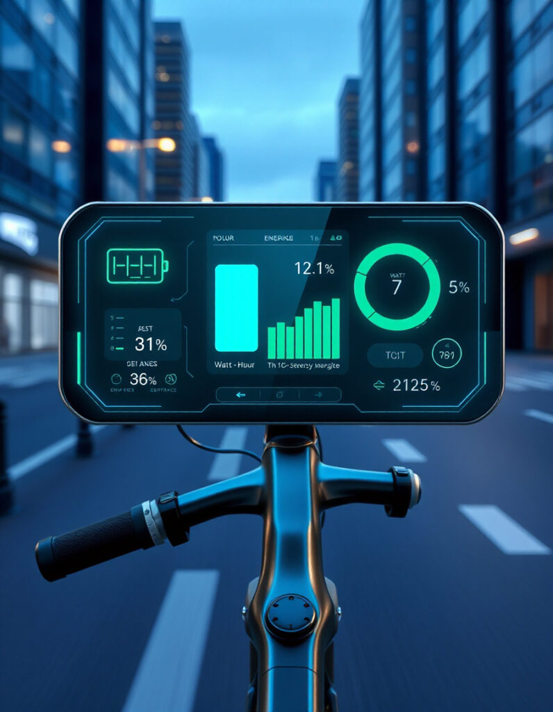
Live Simulation
AI Report
Simulation History PRO
FAQs & Tips
-
Battery runtime is estimated by dividing capacity (Ah) by current draw (A). This tool helps you visualize that behavior in real time under different loads and conditions.
-
Higher voltage increases power output and efficiency, but may also increase heat and stress on components depending on resistance and load.
-
Higher Ah means longer runtime, but it also increases weight, charging time, and cost. The optimal choice depends on your use case.
-
Most lithium batteries perform best between 15°C and 35°C. Higher temperatures can reduce lifespan and increase safety risks.
-
Higher internal resistance leads to energy loss, heat buildup, and reduced performance under load. Lower resistance = healthier battery.
-
They are highly useful for prediction and comparison, but real-world performance still depends on battery quality, age, and environment.
-
E-bike builders, engineers, DIY battery hobbyists, and anyone optimizing lithium battery systems for performance or safety.
Advanced FAQs & Pro Tips
-
BLDC motors typically use 3 phase wires and Hall sensors for commutation, while PMSM motors often rely on more precise electronic control and may include additional feedback systems for smoother torque and efficiency.
-
Power the Hall sensors with 5V, then measure signal output while slowly rotating the motor shaft. A multimeter or oscilloscope helps verify proper pulse switching.
-
Swapping any two phase wires reverses the magnetic rotation sequence, which changes motor direction without affecting performance or efficiency.
-
Most throttles use a 0–5V signal wire (usually white or green) and a ground wire (usually black). Always confirm with a multimeter before connecting to the controller.
-
A brake cutoff wire interrupts motor power when the brake lever is pressed, improving safety by preventing motor engagement during braking.
-
PAS sensors detect pedal rotation using magnets and send a signal to the controller to assist motor output based on pedaling speed and rhythm.
-
Extra wires may be for temperature sensors, encoders, or advanced communication features. Always consult the manufacturer diagram before connecting power.
-
Yes — it helps identify incorrect connections, missing signals, and mismatched wires, making fault detection much faster during repair or installation.
-
Always verify polarity, use proper fuses, connect low voltage first, and test step-by-step instead of powering the full system immediately.
Similar Tools You May Like

🔋 Battery Internal Resistance Estimator
Estimate battery health and performance loss based on internal resistance levels.
⏱️ Charging Time Calculator
Calculate how long your battery needs to fully charge based on amps and capacity.

⚡ Battery Voltage Drop Calculator
Analyze voltage sag under load and improve system efficiency.
🔋 E-Bike Consumption Calculator
Estimate energy usage and optimize riding efficiency for your e-bike system.

⚡ Battery Fuse Size Calculator
Choose the correct fuse size to protect your battery and controller safely.

🌡️ Battery Temperature Impact Tool
Understand how heat and cold affect battery performance and lifespan.
🧩 Battery Pack Builder
Design and simulate custom battery packs for e-bikes and scooters.

🚴 Advanced E-Bike Simulator
Simulate speed, range, heat, and performance of your full e-bike system.
🔧 Similar Tools
This tool is part of the educational resources published on RideWattly. Results should be used as a reference only and not as professional engineering advice.