E-Bike DIY Wiring Color Helper

Identifying e-bike wiring colors correctly is one of the most important steps in any DIY electric bike build or repair. Motor phase wires, Hall sensor cables, throttle signals, brake cutoffs, and controller battery connections must match properly — or you risk poor performance, sensor errors, or even permanent damage.
RideWattly’s Wiring Color Helper gives builders a clear visual reference for BLDC motors, PMSM motors, generic Chinese controllers, and Kelly controllers. Instead of guessing which wire does what, you can quickly verify standard color codes and understand the function behind each connection.
Whether you're replacing a controller, diagnosing a Hall sensor issue, upgrading your throttle, or building a custom pack from scratch, this tool helps you confidently match phase wires (Yellow / Green / Blue), Hall signals, battery leads, PAS wiring, and throttle voltage lines — all in one structured visual guide.
Perfect for DIY riders, home builders, e-bike repair technicians, and advanced hobbyists who want safer, cleaner, and more reliable wiring.
Select your motor or controller below to see standard wiring colors and visual diagrams. Perfect for DIY e-bike projects and safe wiring.
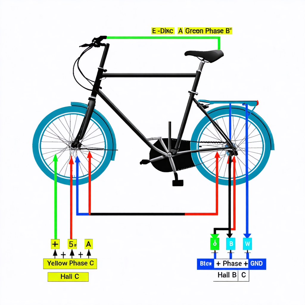
Standard BLDC Motor

| Color | Function | Notes |
|---|---|---|
| Yellow | Phase A | Motor phase wire |
| Green | Phase B | Motor phase wire |
| Blue | Phase C | Motor phase wire |
| Red | +5V / Hall Power | Hall sensors |
| Black | Ground / Hall GND | |
| White | Hall A | Sensor signal |
| Blue | Hall B | Sensor signal |
| Green | Hall C | Sensor signal |
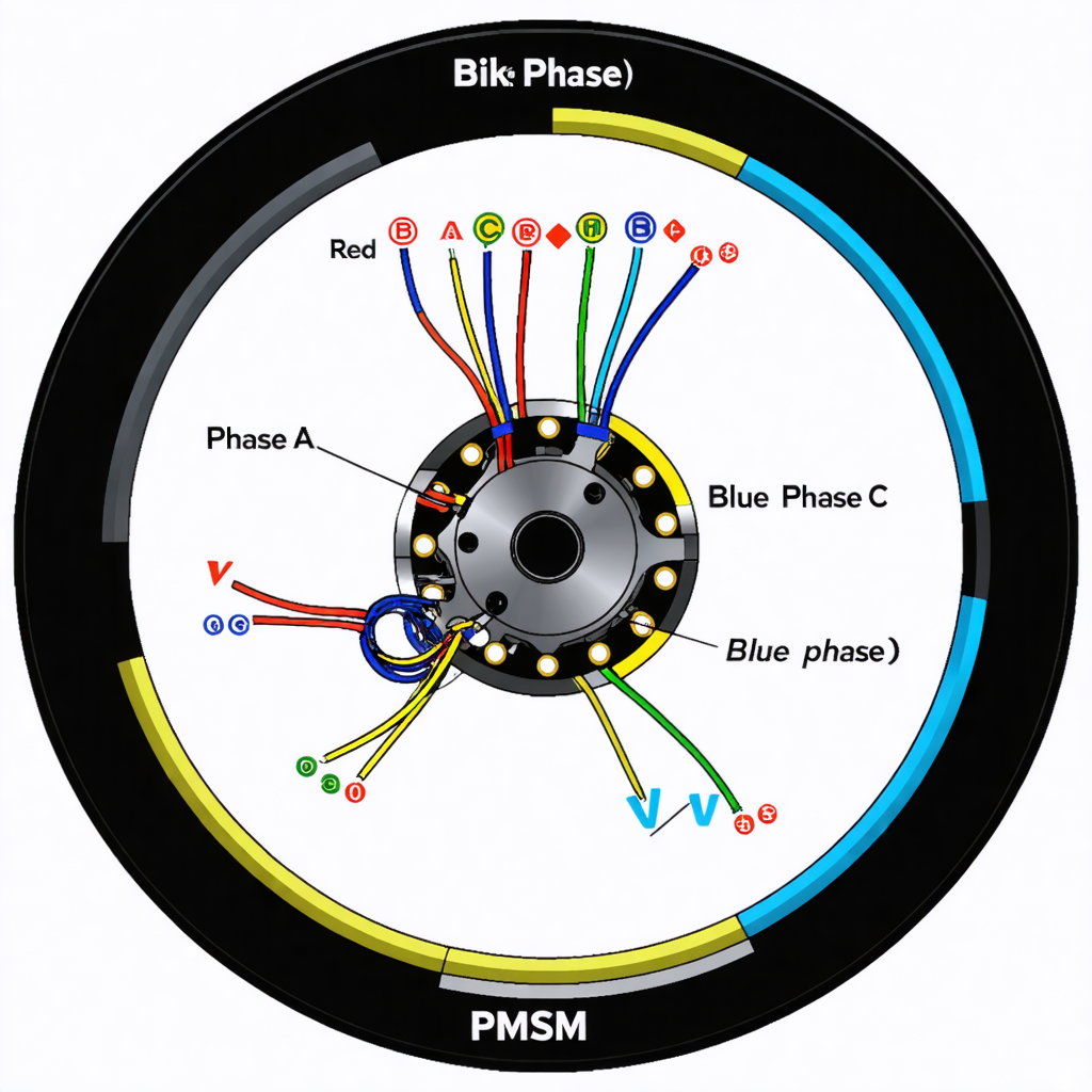
PMSM Motor

| Color | Function | Notes |
|---|---|---|
| Yellow | Phase A | PMSM motor phase |
| Green | Phase B | PMSM motor phase |
| Blue | Phase C | PMSM motor phase |
| Red | +5V / Hall | Hall sensors |
| Black | Ground / Hall GND | |
| White | Hall A | Sensor signal |
| Blue | Hall B | Sensor signal |
| Green | Hall C | Sensor signal |
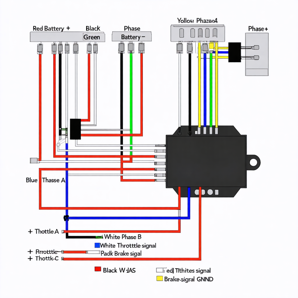
Generic Chinese Controller

| Color | Function | Notes |
|---|---|---|
| Red | Battery + | Connect to battery positive |
| Black | Battery - | Connect to battery negative |
| Yellow | Phase A | Motor phase A |
| Green | Phase B | Motor phase B |
| Blue | Phase C | Motor phase C |
| White | Throttle signal | 0-5V signal |
| Black | Throttle GND | Ground |
| Red/White | Brake signal | Brake lever switch |
| Green | PAS signal | Pedal Assist Sensor |
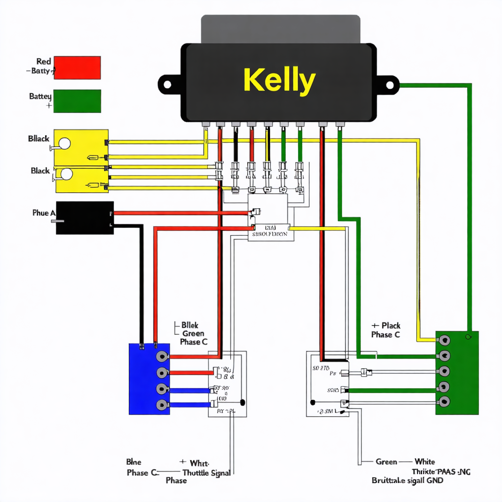
Kelly Controller

| Color | Function | Notes |
|---|---|---|
| Red | Battery + | Connect to battery positive |
| Black | Battery - | Connect to battery negative |
| Yellow | Phase A | Motor phase A |
| Green | Phase B | Motor phase B |
| Blue | Phase C | Motor phase C |
| White | Throttle signal | 0-5V signal |
| Black | Throttle GND | Ground |
| Red/White | Brake signal | Brake lever switch |
| Green | PAS signal | Pedal Assist Sensor |
Common E-Bike Wiring Mistakes to Avoid
Even experienced DIY builders sometimes make wiring errors that can lead to motor malfunction, sensor issues, or battery damage. Understanding these common pitfalls helps you avoid costly mistakes and ensures safe, reliable operation.
- Phase wires mismatch: Connecting Yellow, Green, or Blue wires incorrectly can cause the motor to spin backward or vibrate.
- Hall sensor misconnection: Hall wires (Red, Black, White, Blue, Green) must match the controller inputs exactly to avoid sensor errors or non-starting motor.
- Battery polarity reversal: Connecting positive and negative leads incorrectly can permanently damage the controller or motor.
- Throttle signal mistakes: 0-5V throttle lines (White for signal, Black for GND) must be wired correctly or the throttle will not respond properly.
- Brake cutoff wiring: Mixing up Red/White brake wires can prevent the motor from stopping safely when brakes are applied.
- PAS sensor errors: Miswiring the Green PAS signal can disable pedal assist or trigger erratic motor behavior.
- Loose connections: Ensure all plugs are fully seated and heat shrink or connectors are secure to avoid intermittent faults.
Using RideWattly’s DIY Wiring Color Helper, you can double-check each connection visually, making it easy to catch errors before powering on your e-bike. Safe wiring saves time, protects your components, and improves overall ride reliability.
Start Correct Wiring Now →FAQs & Tips
-
It helps you visually identify standard wiring colors and functions for motors, controllers, throttles, brake cutoffs, and Hall sensors.
-
The tool covers Standard BLDC Motors, PMSM Motors, Generic Chinese Controllers, and Kelly Controllers.
-
Yes, it provides standard wiring references, but always double-check your specific hardware and manufacturer manuals before connecting power.
-
Yes, it clearly identifies Hall sensor wires, power, ground, and signal lines for each motor type.
-
Absolutely — the tool shows standard 0-5V throttle signals and brake cutoff wire functions.
-
Yes, RideWattly provides it freely for DIY enthusiasts, home builders, and repair technicians.
Advanced FAQs & Pro Tips
-
BLDC motors usually have 3 phase wires (Yellow, Green, Blue) and Hall sensors, while PMSM motors may have additional feedback wires for precise rotor position control.
-
Use a 5V supply for Hall power, check continuity to ground, and verify signal pulses with a multimeter or oscilloscope while rotating the motor shaft slowly.
-
Yes, swapping any two phase wires (Yellow/Green/Blue) reverses rotation direction without affecting performance.
-
Typically, White is the throttle signal (0-5V), and Black is ground. Verify with a multimeter before connecting to the controller.
-
The brake cutoff wire (often Red/White) connects to a brake lever switch; it cuts motor power when brakes are applied to ensure safety.
-
Connect the PAS signal wire (Green) to the designated controller input, power the sensor properly, and ensure the magnet disc aligns with the sensor.
-
Extra wires may be for temperature sensors, encoders, or advanced features. Check the manufacturer’s manual before connecting.
-
Yes, it helps identify wire functions visually, making it easier to detect miswiring, sensor faults, or disconnected phase wires.
Related Tools & Resources

💻 RideWattly IDE PRO
Advanced coding and SEO-friendly environment for web projects.
🛠️ Smart Controller Helper
Test and program e-bike controllers safely with visual assistance.
🎨 E-Bike Wiring Diagram Helper
Visualize and verify motor, throttle, brake, and PAS wiring diagrams.
🛞 Tire Pressure Advisor
Check and optimize your e-bike or e-scooter tire pressure for better ride performance.
🗺️ Smart Route Planner
Plan efficient routes for e-bikes and scooters using real-time data.
🛴 Electric Scooter Comparison
Compare specs, motors, and battery performance across electric scooters.
🔧 Similar Tools
This tool is part of the educational resources published on RideWattly. Results should be used as a reference only and not as professional engineering advice.