🔍 E-Bike Wiring Diagram Helper
Visualize, design and export your e-bike electrical wiring. Learn each component and get step-by-step guidance for the tool.
The E-Bike Wiring Diagram Helper is an interactive visual tool that helps you place components (battery, controller, motor, BMS, etc.), auto-draws logical connections, and export the diagram for documentation. It supports smart visual cues (power, signal, communication), save/load, and Undo/Redo.
Quick Summary
Why wiring matters
Good wiring design ensures safe current flow, reliable communications between control units, and effective protection against faults. Visualizing the wiring helps prevent errors, plan for routing, and document the build for future maintenance.
Components & What They Do
Battery
The main energy source. Typical e-bike packs: 36V, 48V, or 52V. The battery supplies current to the controller, BMS and other loads (lights, accessories).
Controller
The controller is the power management brain: it regulates motor current, interprets throttle/pedal signals and controls regenerative braking in some systems.
Motor
Converts electrical energy to mechanical torque. Common types: hub motors (rear/front) and mid-drive motors (at the crank).
BMS (Battery Management System)
Protects and balances the cells: prevents overcharge, overdischarge, short circuits and monitors temperature. Vital for safety and battery longevity.
Charger
Recharges the battery from AC mains. Chargers can connect to the battery via a charge port and often communicate with the BMS.
Fuse
Protective device that opens on overload or short-circuit. Placed on high-current lines to prevent catastrophic failures.
Switch
On/off control for the system or accessories. A simple mechanical or electronic switch that isolates battery output when off.
Throttle
User input that requests power from the controller. Throttle signals are interpreted by the controller to adjust motor output.
Display
Shows speed, battery level, assist level, and sometimes diagnostics. May communicate with the controller for richer functions.
Types of connections (what the lines mean)
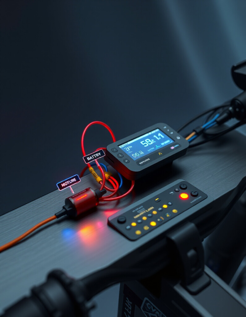
Power connection (red) — high current routes, e.g., Battery → Controller → Motor.
Signal connection (blue) — low-voltage control or status lines, e.g., Display ↔ Controller, Throttle → Controller.
Communication (green) — data or auxiliary links, e.g., advanced displays, BMS telemetry, or throttle communications.
How to use the E-Bike Wiring Diagram Helper
Step 1 — Add components
From the left panel click Add to insert components into the canvas. Start with the battery and controller, then add motor, BMS, throttle and other parts.
Step 2 — Arrange and align
Drag components to create a logical layout. Use Ctrl+click to multi-select and drag multiple items together. The tool snaps to a grid for neat alignment.
Step 3 — Smart connections
The application draws connections automatically between compatible components using the system rules (power → controller → motor, etc.). Hover a connection to see its type and short description.
Step 4 — Export & save
Use Export PNG/PDF to create printable documentation. Choose high resolution if you need print-quality outputs. Use Save JSON to keep an editable copy for later.
Step 5 — Undo / Redo
If you make a mistake, use Undo or Redo to step through change history (adds, deletes and moves are tracked).
Tip
Layout your battery, controller, and motor first — these are the backbone of the wiring. Add protective devices (fuse, BMS) close to the battery in the diagram for clarity.
Best practices for wiring & layout
- Short high-current runs: Keep the main positive/negative paths between battery, controller and motor as short and thick as practical to reduce loss and heat.
- Protective placement: Place fuses or circuit breakers at the battery positive terminal before branching to other loads.
- Thermal awareness: Keep high-current devices away from heat-sensitive components and allow ventilation.
- Document everything: Export and save diagrams before testing — it saves troubleshooting time later.
Troubleshooting & common issues
No motor response: Check battery voltage, main fuse and controller power input. Verify the controller-to-motor connectors.
Throttle not working: Check signal wiring to the controller and whether the display or throttle requires specific communication protocols.
Battery heating/imbalance: Ensure BMS is present and cells are balanced; verify charger compatibility with the battery chemistry.
Ready-to-use snippets (for your documentation)
Copy this example caption for use under the exported diagram:
Diagram shows the battery powering the controller which drives the motor. BMS and fuse protect the battery; throttle and display are low-voltage interfaces to the controller.
Want this page adapted for your site template? I can convert this content into a shortcode, Gutenberg block, or a theme-ready HTML partial. Tell me which CMS or theme you use (WordPress, static site, etc.) and I’ll adapt it.