E-Bike Wiring Diagram Builder (DIY Motor & Controller Tool)

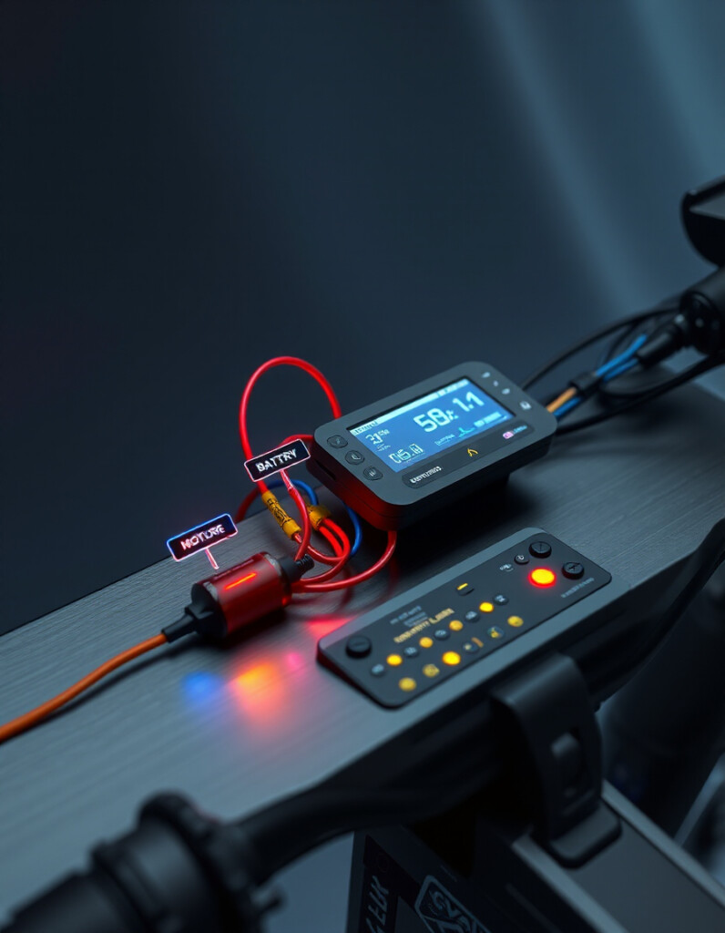
Understanding e-bike wiring connections is essential for safely assembling, modifying, or troubleshooting your electric bike system. This includes correctly linking the controller, throttle, brakes, sensors, lights, and battery to ensure optimal performance and prevent damage.
RideWattly’s E-Bike Wiring Diagram Helper allows hobbyists, technicians, and advanced riders to interactively visualize wiring layouts. Hover on connections for detailed info, drag components, and instantly see how everything connects in a clear and safe schematic.
Whether you're installing a new motor, replacing a controller, or diagnosing a wiring issue, this tool provides real-time guidance, undo/redo functionality, and options to save, load, or export your wiring diagrams as PNG or PDF.
Hover on connections to see info. Drag components, save/load, or export as PNG/PDF. Undo/Redo supported.
Components
FAQs & Tips
-
It is an interactive tool that visually maps standard wiring connections for e-bike components, including motors, controllers, batteries, throttles, brakes, sensors, and lights.
-
The tool includes Standard BLDC Motors, PMSM Motors, generic Chinese and Kelly controllers, throttles, brake cutoffs, Hall sensors, displays, BMS, and batteries.
-
Yes, it provides standard wiring references, but always verify your specific components and manufacturer manuals before applying power.
-
Yes, the tool clearly identifies Hall sensor wires (power, ground, signal) and standard 0-5V throttle wiring for supported controllers.
-
Absolutely — you can export diagrams as PNG or PDF, save and load JSON files, or embed the diagram on your own website.
-
Yes, RideWattly provides the Wiring Diagram Helper free for DIY enthusiasts, repair technicians, and hobbyists.
-
Yes, you can drag components, hover over connections for info, undo/redo actions, and dynamically build your wiring layout.
Advanced FAQs & Pro Tips
-
BLDC motors usually have 3 phase wires (Yellow, Green, Blue) and Hall sensors, while PMSM motors may have additional feedback wires for precise rotor position control.
-
Use a 5V supply for Hall power, check continuity to ground, and verify signal pulses with a multimeter or oscilloscope while rotating the motor shaft slowly.
-
Yes, swapping any two phase wires (Yellow/Green/Blue) reverses rotation direction without affecting performance.
-
Typically, White is the throttle signal (0-5V), and Black is ground. Always verify with a multimeter before connecting to the controller.
-
The brake cutoff wire (often Red/White) connects to a brake lever switch; it cuts motor power when brakes are applied to ensure safety.
-
Connect the PAS signal wire (Green) to the designated controller input, power the sensor properly, and ensure the magnet disc aligns with the sensor.
-
Extra wires may be for temperature sensors, encoders, or advanced features. Check the manufacturer’s manual before connecting.
-
Double-check all wire colors, ensure proper polarity, use fuses, and power on briefly while monitoring voltage and current carefully.
-
Yes, it helps identify wire functions visually, making it easier to detect miswiring, sensor faults, or disconnected phase wires.
-
While primarily for standard controllers, the visual color references can guide you for similar models. Always measure voltages and verify connections before applying power.
Related Tools & Resources
🎨 E-Bike Wiring Diagram Helper
Visual guide to e-bike motor, controller, PAS and throttle wiring.
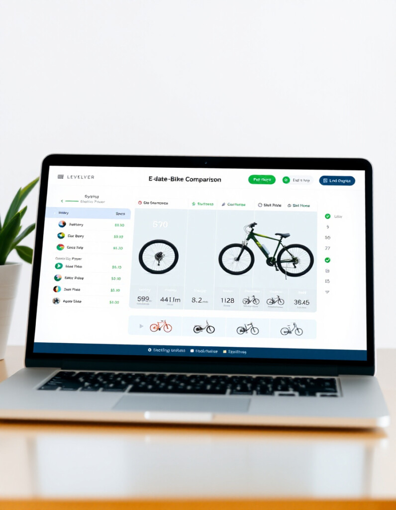
📊 E-Bike Spec & Comparison Tool
Compare e-bike models, motors, batteries and components in detail.
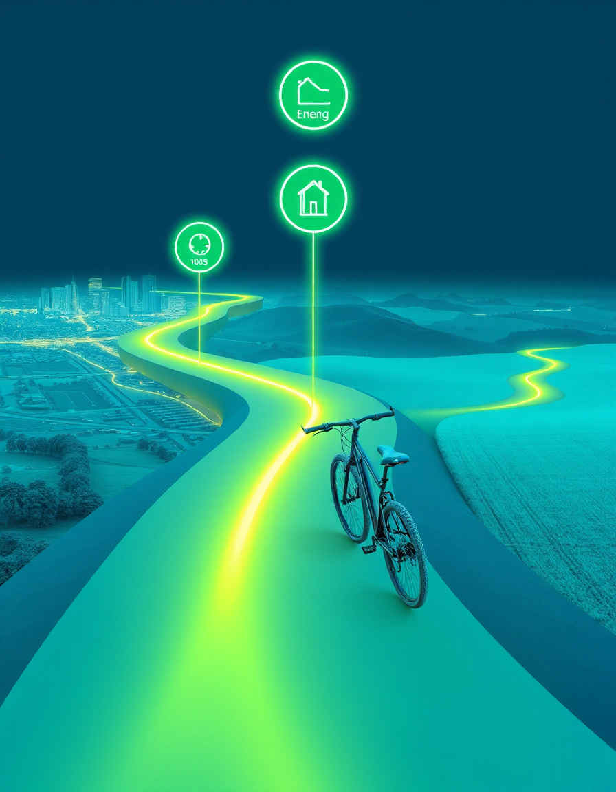
🗺️ Smart Route Planner
Plan efficient routes for e-bikes and scooters using real-time data.
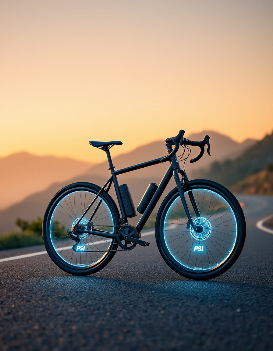
🛞 Tire Pressure Advisor
Check and optimize your tire pressure for better ride comfort and performance.
🛴 E-Scooter Range Calculator
Estimate realistic scooter ranges based on battery and terrain conditions.

🚴♂️ Advanced E-Bike Simulator
Simulate different e-bike setups to test performance, speed, and battery usage.

🔋 Battery Pack Thermal Calculator
Calculate voltage, capacity, and configuration for custom e-bike battery packs.
⚙️ Motor Power & Efficiency Calculator
Estimate motor efficiency, power output, and performance under different loads.
🔧 Similar Tools
This tool is part of the educational resources published on RideWattly. Results should be used as a reference only and not as professional engineering advice.